The sensor setup for the real-world tests scenarios was mounted on a Smart ForTwo electric vehicle, as shown in the Figures bellow, and consists of the following sensors:
- Camera Sekonix SF3325-100, 1920x1232 resolution (2.3M Pixel), 30Hz capture frequency, H:60°;V:36,6°
- Radar Continental ARS408-21, FMCW, ≤ 250m range, 13Hz capture frequency, 77 GHz operating frequency band, ±0.1 km/h vel.accuracy
- LiDAR Ouster OS1-128, 10hz capture frequency, resolution 1024.
- Inertial Measurement Unit (IMU) Gensys ADMA- G PRO, 100Hz capture frequency, resolution 0.01m/0.005°
- GNSS (Global Navigation Satellite System) SP80, res- olution 0.008m, 10Hz capture frequency
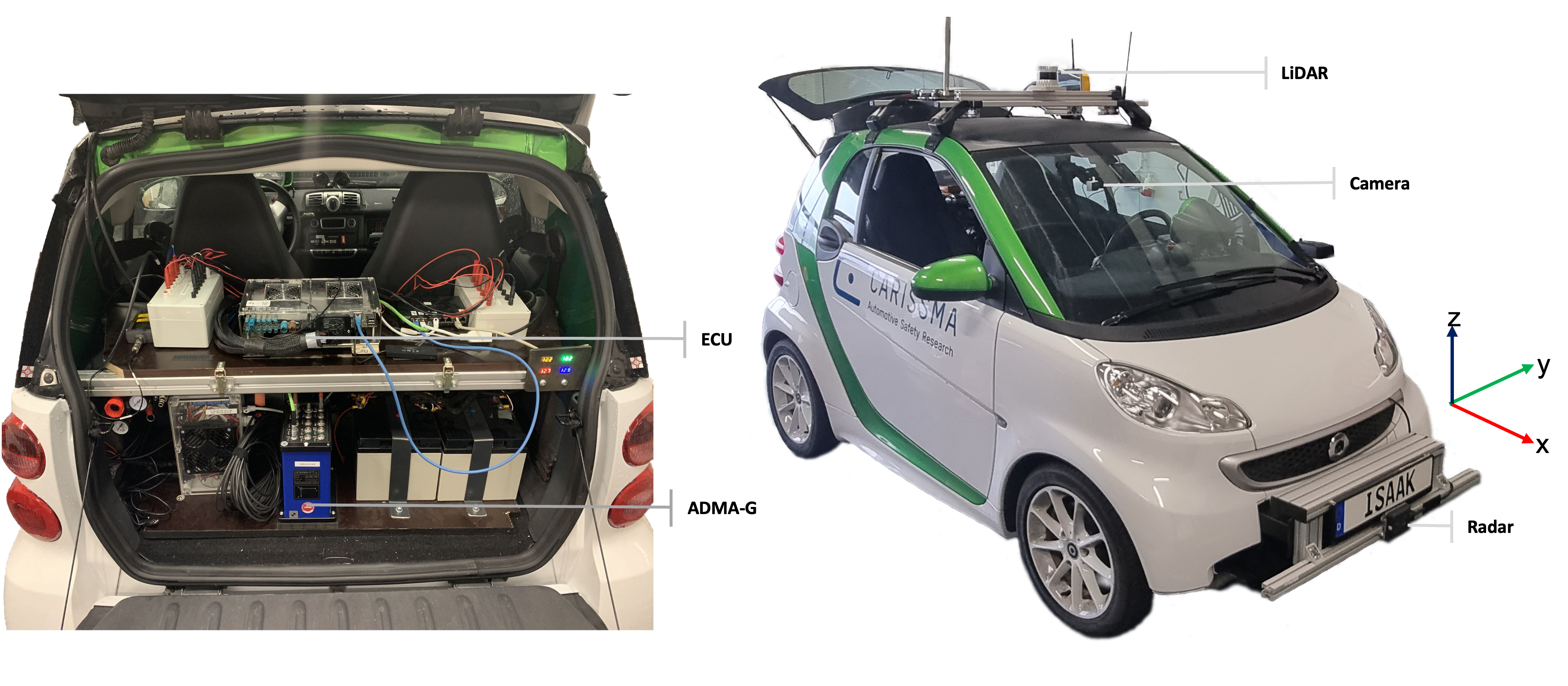
The data is acquired in real-time using ROS running on the Nvidia DRIVEPX2, in which all sensors are connected. The radar was positioned in front bumper of the ego-vehicle, the camera inside the car attached to the windshield, the LiDAR on the car’s roof, and the IMU in the trunk alongside the ECU. To capture the precise location of the pedestrian, cyclist, and truck, we utilized GNSS SP80 sensor. When the object of interest was a car, we used an identical Smart ForTwo vehicle equipped with the same IMU. The radar data was recorded with two different types of operation mode: cluster which is a point cloud where each point is a radar reflection and object list which these reflections are condensed into bounding boxes objects. In both cases, radar detections have velocity, position and RCS (Radar cross Section).
The position of the objects and the ego-vehicle is given in a relative coordinate system with respect to a reference point on the track. The sensors use the position of the ego-vehicle as the reference frame, following the convention shown in Figure above. The X-axis points forward, the Y-axis points to the left, and the Z-axis points upward.
Laboratory. In the laboratory, the HIL test environment consists of the same hardware and software stack for the environment perception sensors (except the lidar and IMU), and includes the following additional equipment:
• NI PXIe-8115 Controller;
• NI PXIe-1085 Chassis with CAN modules (National Instruments);
• Vehicle Radar Test System (VRTS) (Konrad Technologies);
• Video Interface Box (IPG Automotive);
• Camera-Box (article);
• Environment Simulation Software CarMaker (IPG Automotive);
As it can be seen, the setup is a hardware-in-the-Loop test environment, in which real sensors (radar and camera) are stimulated so that they can perceive the objects in the environment simulation software (CarMaker).